Contemporary Supercritical Steam generators are sometimes referred as Benson boilers. In 1922 , Mark Benson was granted a patent for a boiler designed to convert water into steam at high pressure.
Safety was the main concern behind Benson's concept. Earlier steam generators were designed for relatively low pressures of up to about 100 bar (10,000kpa ; 1,450psi) , corresponding to the state of the art in steam turbine development at the time. One of their distinguishing technical characteristics was the riveted water/steam separator drum. These drums were where the water filled tubes were terminated after having passed through the boiler furnace.
These header drums were intended to be partially filled with water and above the water there was a baffle filled space where the boiler's steam and water vapour collected. The entrained water droplets were collected by the baffles and returned to the water pan. The mostly dry steam was piped out of the drum as the separated steam output of the boiler. these drums were often the source of boiler explosions , usually with catastrophic consequences.
However , this drum could be completely eliminated if the evaporation separation process was avoided altogether. This would happen if water entered the boiler at a pressure above the critical pressure (3,206) ; was heated to a temperature above the critical temperature (706 degrees F) and then expanded (through a simple nozzle) to dry steam at some lower subcritical pressure. This could be obtained at a throttle valve located downstream of the evaporator section of the boiler.
As development of Benson technology continued , boiler design soon moved away from the original concept introduced by Mark Benson. In 1929 , a test boiler that had been built in 1927 began operating in the thermal power plant at Gartenfeld in Berlin for the first time in subcritical mode with a fully open throttle valve. The second Benson boiler began operation in 1930 without a pressurizing valve at pressures between 40and 180 bar (4,000 and 18,000 kpa ; 580 and 2,611 psi) at the Berlin cable factory. This application represented the birth of the modern variable-pressure Benson boiler. After that development , the original patent was no longer used. The Benson boiler name , however , was retained.
Two current innovations have a good chance of winning acceptance in the competitive market for once-through steam generators :
* A new type of heat-recovery steam generator based on the Benson boiler , which has operated
successfully at the Cottam combined-cycle power plant in the central part of England ,
* The vertical tubing in the combustion chamber walls of coal-fired steam generators which combines
the operating advantages of the Benson system with the design advantages of the drum-type boiler.
Construction of a first reference plant , the Yaomeng power plant in china , commenced in 2001.
Sunday, February 20, 2011
Friday, January 21, 2011
Supercritical steam generators
Supercritical steam generators (also known as Benson boilers) are frequently used for the production of electric power. They operate at "supercritical pressure". In contrast to a "subcritical boiler" , a supercritical steam generator operates at such a high pressure (over 3,200psi/22.06MPa or 220.6bar) that actual boiling ceases to occur , and the boiler has no water - steam separation. There is no generation of steam bubbles within the water , because the pressure is above the "critical pressure" at which steam bubbles can form. It passes below the critical point as it does work in the high pressure turbine and enters the generator's condenser. This is more efficient , resulting in slightly less fuel use. The term "boiler" should not be used for a supercritical pressure steam generator , as no "boiling" actually occurs in this device.
Friday, December 17, 2010
Superheated steam boilers
 |
| A superheated boiler on a steam locomotive |
Most boilers produce steam to be used at saturation temperature ; that is , saturated steam. Superheated steam boilers vaporize the water and then further heat the steam in a superheater. This provides steam at much higher temperature , bur can decrease the overall thermal efficiency of the steam generating plant because the higher steam temperature requires a higher flue gas exhaust temperature. There are several ways to circumvent this problem , typically by providing an economizer that heats the feed water , a combustion air heater in the hot flue gas exhaust path or both. There are advantages to superheated steam that may and often will , increase overall efficiency of both steam generation and its utilisation: gains in input temperature to a turbine should outweigh any cost in additional boiler complication and expense. There may also be practical limitations in using wet steam , as entrained condensation droplets will damage turbine blades.
Superheated steam presents unique safety concerns because , if any system component fails and allows steam to escape , the high pressure and temperature can cause serious , instantaneous harm to anyone in its path. Since the escaping steam will initially be completely superheated vapor , detection can be difficult , although the intense heat and sound from such a leak clearly indicates its presense.
Superheater operation is similar to that of the coils on an air conditioning unit , although for a different purpose. The steam piping is directed through the flue gas path in the boiler furnace. The temperature in this area is typically between 1,300-1,600 degree Celsius (2,372-2,912°F). Some superheaters are radiant type ; that is , they absorb heat by radiation. Others are convection type , absorbing heat from a fluid such as a gas. Some are a combination of the two types. Through either method , the extreme heat in the flue gas path will also heat the superheater steam piping and the steam within. While the temperature of the steam in the superheater rises , the pressure of the steam does not : the turbine or moving pistons offer a continuously expanding space and the pressure remains the same as that of the boiler. Almost all steam superheater system designs remove droplets entrained in the steam to prevent damage to the turbine blading and associated piping.
Tuesday, December 7, 2010
Hydronic Boilers
Hydronic Boilers
Hydronic boilers are used in generating heat for residential and industrial purposes. They are the typical power plant for central heating systems fitted to houses in northern Europe (where they are commonly combined with domestic water heating) , as apposed to the forced-air furnaces or wood burning stoves more common in North America. The hydronic boiler operates by way of heating water/fluid to a preset temperature (or sometimes in the case of single pipe systems , until it boils and turns to steam) and circulating that fluid throughout the home typically by way of radiators , baseboard heaters or through the floors. The fluid can be heated by any means...gas , wood , fuel oil etc.. , but in built-up areas where piped gas is available , natural gas is currently the most economical and therefore the usual choice. The fluid is in an enclosed system and circulated throughout by means of a motorized pump. The name "boiler" can be a misnomer in that , except for systems using steam radiators , the water in a properly functioning hydronic boiler never actually boils. Most new systems are fitted with condensing boilers for greater efficiency. These boilers are referred to as condensing boilers because they condense the water vapor in the flue gases to capture the latent heat of vaporization of the water produced during combustion.
Hydronic systems are being used more and more in new construction in North America for several reasons. Among the reasons are :
* They are more efficient and more economical than forced-air systems (although initial installation can be
more expensive , because of the cost of the copper and aluminium).
* The baseboard copper pipes and aluminium fins take up less room and use less metal than the bulky steel
ductwork required for forced-air systems.
* They provide more even , less fluctuating temperatures than forced-air systems. The copper baseboard pipe
hold and release heat over a longer period of time than air does , so the furnace does not have to switch off
and on as much.(Copper heats mostly through conduction and radiation , whereas forced-air heats mostly
through forced convection. Air has much lower thermal conductivity and volumetric heat capacity than
copper , so the conditioned space warms up and cools down more quickly than with hydronic)
* They tend to not dry out the interior air as much as forced air systems , but this is not always true. When
forced air duct systems are air-sealed properly and have return-air paths back to the furnace (thus reducing
pressure differentials and therefore air movement between inside and outside the house) this is not an issue.
* They do not introduce any dust , allergens , mold or (in the case of a faulty heat exchanger) combustion by
products into the living space.
Forced-air heating does have some advantages , however.
Hydronic boilers are used in generating heat for residential and industrial purposes. They are the typical power plant for central heating systems fitted to houses in northern Europe (where they are commonly combined with domestic water heating) , as apposed to the forced-air furnaces or wood burning stoves more common in North America. The hydronic boiler operates by way of heating water/fluid to a preset temperature (or sometimes in the case of single pipe systems , until it boils and turns to steam) and circulating that fluid throughout the home typically by way of radiators , baseboard heaters or through the floors. The fluid can be heated by any means...gas , wood , fuel oil etc.. , but in built-up areas where piped gas is available , natural gas is currently the most economical and therefore the usual choice. The fluid is in an enclosed system and circulated throughout by means of a motorized pump. The name "boiler" can be a misnomer in that , except for systems using steam radiators , the water in a properly functioning hydronic boiler never actually boils. Most new systems are fitted with condensing boilers for greater efficiency. These boilers are referred to as condensing boilers because they condense the water vapor in the flue gases to capture the latent heat of vaporization of the water produced during combustion.
Hydronic systems are being used more and more in new construction in North America for several reasons. Among the reasons are :
* They are more efficient and more economical than forced-air systems (although initial installation can be
more expensive , because of the cost of the copper and aluminium).
* The baseboard copper pipes and aluminium fins take up less room and use less metal than the bulky steel
ductwork required for forced-air systems.
* They provide more even , less fluctuating temperatures than forced-air systems. The copper baseboard pipe
hold and release heat over a longer period of time than air does , so the furnace does not have to switch off
and on as much.(Copper heats mostly through conduction and radiation , whereas forced-air heats mostly
through forced convection. Air has much lower thermal conductivity and volumetric heat capacity than
copper , so the conditioned space warms up and cools down more quickly than with hydronic)
* They tend to not dry out the interior air as much as forced air systems , but this is not always true. When
forced air duct systems are air-sealed properly and have return-air paths back to the furnace (thus reducing
pressure differentials and therefore air movement between inside and outside the house) this is not an issue.
* They do not introduce any dust , allergens , mold or (in the case of a faulty heat exchanger) combustion by
products into the living space.
Forced-air heating does have some advantages , however.
Monday, November 29, 2010
Boiler Accessories
Boiler fittings and accessories
* Safety valve :
It is used to relieve pressure and prevent possible explosion of a boiler.
* Water level indicators :
They show the operator the level of fluid in the boiler , also known as a sight glass , water gauge orwater column is provided.
* Bottom blowdown valves :
They provide a means for removing solid particulates that condense and lie on the bottom of a boiler. As the name implies , this valve is usually located directly on the bottom of the boiler and is occasionally opened to use the pressure in the boiler to push these particulates out.
* Continuous blowdown valve :
This allows a small quantity of water to escape continuously. Its purpose is to prevent the water in the boiler becoming saturated with dissolved salts. Saturation would lead to foaming and cause water droplets to be carried over with the steam - a condition known as priming. Blowdown is also often used to monitor the chemistry of the boiler water.
* Flash tank :
High pressure blowdown enters this vessel where the steam can 'flash' safely and be used in a low-pressure system or be vented to atmosphere while the ambient pressure blowdown flows to drain.
* Automatic blowdown/continuous Heat Recovery system :
This system allows the boiler to blowdown only when makeup water is flowing to the boiler , thereby transferring the maximum amount of heat possible from the blowdown to the makeup water. No flash tank is generally needed as the blowdown discharged is close to the temperature of the makeup water.
* Hand holes :
They are steel plates installed in openings in "header" to allow foe inspections & installation of tubes and inspection of internal surfaces.
* Steam drum internals :
A series of screen , scrubber & cans(cyclone separators).
* Low-water cutoof :
It is a mechanical means (usually a float switch) that is used to turn off the burner of shut off fuel to the boiler to prevent it from running once the water goes below a certain point. If a boiler is "dry-fired" (burned without water in it) it can cause rupture or catastrophic failure.
* Surface blowdown line :
It provides a means for removing form or other lightweight non-condensible substance that tend to float on top of the water inside the boiler.
* Circulating pump :
It is designed to circulate water back to the boiler after it has expelled some of its heat.
* Feedwater check valve or clack valve :
A non-return stop valve in the feedwater line. This may be fitted to the side of the boiler , just below the water level or to the top of the boiler.
* Top feed :
A check valve (clack valve) in the feedwater line , mounted on top of the boiler. It is intended to reduce the nuisance of limescale. It does not prevent limescale formation but causes the limescale to be precipitaed in a powdery form which is easily washed out of the boiler.
* Desuperheater tubes or bundles :
A series of tubes or bundles of tubes in the water drum or the steam drum design to cool superheated steam. Thus is to supply auxiliary equipment that doesn't need or may be damaged by or dry system.
* Chemical injection line:
A connection to add chemicals for controlling feedwater pH.
* Safety valve :
It is used to relieve pressure and prevent possible explosion of a boiler.
* Water level indicators :
They show the operator the level of fluid in the boiler , also known as a sight glass , water gauge orwater column is provided.
* Bottom blowdown valves :
They provide a means for removing solid particulates that condense and lie on the bottom of a boiler. As the name implies , this valve is usually located directly on the bottom of the boiler and is occasionally opened to use the pressure in the boiler to push these particulates out.
* Continuous blowdown valve :
This allows a small quantity of water to escape continuously. Its purpose is to prevent the water in the boiler becoming saturated with dissolved salts. Saturation would lead to foaming and cause water droplets to be carried over with the steam - a condition known as priming. Blowdown is also often used to monitor the chemistry of the boiler water.
* Flash tank :
High pressure blowdown enters this vessel where the steam can 'flash' safely and be used in a low-pressure system or be vented to atmosphere while the ambient pressure blowdown flows to drain.
* Automatic blowdown/continuous Heat Recovery system :
This system allows the boiler to blowdown only when makeup water is flowing to the boiler , thereby transferring the maximum amount of heat possible from the blowdown to the makeup water. No flash tank is generally needed as the blowdown discharged is close to the temperature of the makeup water.
* Hand holes :
They are steel plates installed in openings in "header" to allow foe inspections & installation of tubes and inspection of internal surfaces.
* Steam drum internals :
A series of screen , scrubber & cans(cyclone separators).
* Low-water cutoof :
It is a mechanical means (usually a float switch) that is used to turn off the burner of shut off fuel to the boiler to prevent it from running once the water goes below a certain point. If a boiler is "dry-fired" (burned without water in it) it can cause rupture or catastrophic failure.
* Surface blowdown line :
It provides a means for removing form or other lightweight non-condensible substance that tend to float on top of the water inside the boiler.
* Circulating pump :
It is designed to circulate water back to the boiler after it has expelled some of its heat.
* Feedwater check valve or clack valve :
A non-return stop valve in the feedwater line. This may be fitted to the side of the boiler , just below the water level or to the top of the boiler.
* Top feed :
A check valve (clack valve) in the feedwater line , mounted on top of the boiler. It is intended to reduce the nuisance of limescale. It does not prevent limescale formation but causes the limescale to be precipitaed in a powdery form which is easily washed out of the boiler.
* Desuperheater tubes or bundles :
A series of tubes or bundles of tubes in the water drum or the steam drum design to cool superheated steam. Thus is to supply auxiliary equipment that doesn't need or may be damaged by or dry system.
* Chemical injection line:
A connection to add chemicals for controlling feedwater pH.
Friday, November 19, 2010
Safty
 |
| What Caused the Boiler Explosion at the Ford Rouge Plant |
 |
| Boiler Explosion At York Rolling MIlls Kills 9 Men; 20 injured |
A boiler that has a loss of feed water and is permitted to boil dry can be extremely dangerous. If feed water is then sent into the empty boiler , the small cascade of incoming water instantly boils on contact with the superheated metal shell and leads to a violent explosion that cannot be controlled even by safety steam valves. Draining of the boiler could also occur if a leak occurred in the steam supply lines that was larger than the make-up water supply could replace. The Hartford Loop was invented in 1919 by the Hartford Steam Boiler and insurance company as a method to help prevent this condition from occurring and thereby reduce their insurance claims.
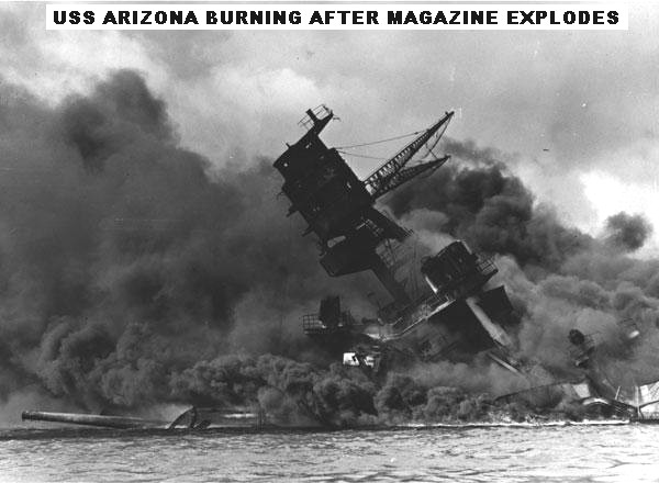 |
| A boiler explosion would not have caused the forward decks to collapse |
Thursday, November 18, 2010
Configurations
Configurations
Boilers can be classified into the following configurations :
* "Port boilers" or "Haycock boilers" : a primitive "kettle" where a fire heats a partially-filled water container
from below. 18th century Haycock boilers generally produced and stored large volumes of very
low-pressure
steam , often hardly above that of the atmosphere. These could burn wood of most often , coal. Efficiency
was very low.
* Fire-tube boilers. Here , water partially fills a boiler barrel with a small volume left above to accommodate
the steam (steam space). This is the type of boilers used in nearly all steam locomotives. The heat source is
inside a furnace or firebox that has to be kept permanently surrounded by the water in order to maintain the
temperature of the heating surface just below boiling point. The furnace can be situated at one end of
fire-tube which lengthens the path of the hot gases , thus augmenting the heating surface which can be
further increased by making the gases reverse direction through a second parallel tube or a bundle of
multiple tubes (two-pass or return flue boiler) ; alternatively the gases may be taken along the sides and then
beneath the boiler through flues (3-pass boiler). In the case of a locomotive-type boiler , a boiler barrel
extends from the firebox and the hot gases pass through a bundle of fire tubes inside the barrel which
greatly increase the heating surface compared to a single tube and further improve heat transfer. Fire-tube
boilers usually have a comparatively low rate of steam production , but high steam storage capacity.
Fire-tube boilers mostly burn solid fuels, but are readily adaptable to those of the liquid or gas variety.
* Water-tube boiler. In this type , the water tubes are arranged inside a furnace in a number of possible
configurations : often the water tubes connect large drums , the lower ones containing water and the upper
ones , steam and water ; in other cases , such as a monotube boiler , water is circulated by a pump through
a succession of coils. This type generally gives high steam production rates , but less storage capacity than
the above. Water tube boilers can be designed to exploit any heat source and are generally preferred in high
pressure applications since the high pressure water/steam is contained within small diameter pipes which can
withstand the pressure with a thinner wall.
* Flash boiler. A specialized type of water-tube boiler.
1950s design steam locomotive boiler , from a victorian Railways J class
* Fire-tube boiler with water-tube firebox. Sometimes the two above types have been combined in the
following manner : the firebox contains an assembly of water tubes , called thermic syphons. The gases
then pass through a conventional firetube boilers. Water-tube firebox were installed in many Hungarian
locomotives , but have met with little success in other countries.
* Sectional boiler. In a cast iron sectional boiler , sometimes called a "pork chop boiler" the water is
contained inside cast iron sections. These sections are assembled on site to create the finished boiler.
Boilers can be classified into the following configurations :
* "Port boilers" or "Haycock boilers" : a primitive "kettle" where a fire heats a partially-filled water container
from below. 18th century Haycock boilers generally produced and stored large volumes of very
low-pressure
steam , often hardly above that of the atmosphere. These could burn wood of most often , coal. Efficiency
was very low.
* Fire-tube boilers. Here , water partially fills a boiler barrel with a small volume left above to accommodate
the steam (steam space). This is the type of boilers used in nearly all steam locomotives. The heat source is
inside a furnace or firebox that has to be kept permanently surrounded by the water in order to maintain the
temperature of the heating surface just below boiling point. The furnace can be situated at one end of
fire-tube which lengthens the path of the hot gases , thus augmenting the heating surface which can be
further increased by making the gases reverse direction through a second parallel tube or a bundle of
multiple tubes (two-pass or return flue boiler) ; alternatively the gases may be taken along the sides and then
beneath the boiler through flues (3-pass boiler). In the case of a locomotive-type boiler , a boiler barrel
extends from the firebox and the hot gases pass through a bundle of fire tubes inside the barrel which
greatly increase the heating surface compared to a single tube and further improve heat transfer. Fire-tube
boilers usually have a comparatively low rate of steam production , but high steam storage capacity.
Fire-tube boilers mostly burn solid fuels, but are readily adaptable to those of the liquid or gas variety.
* Water-tube boiler. In this type , the water tubes are arranged inside a furnace in a number of possible
configurations : often the water tubes connect large drums , the lower ones containing water and the upper
ones , steam and water ; in other cases , such as a monotube boiler , water is circulated by a pump through
a succession of coils. This type generally gives high steam production rates , but less storage capacity than
the above. Water tube boilers can be designed to exploit any heat source and are generally preferred in high
pressure applications since the high pressure water/steam is contained within small diameter pipes which can
withstand the pressure with a thinner wall.
* Flash boiler. A specialized type of water-tube boiler.
1950s design steam locomotive boiler , from a victorian Railways J class
* Fire-tube boiler with water-tube firebox. Sometimes the two above types have been combined in the
following manner : the firebox contains an assembly of water tubes , called thermic syphons. The gases
then pass through a conventional firetube boilers. Water-tube firebox were installed in many Hungarian
locomotives , but have met with little success in other countries.
* Sectional boiler. In a cast iron sectional boiler , sometimes called a "pork chop boiler" the water is
contained inside cast iron sections. These sections are assembled on site to create the finished boiler.
Subscribe to:
Posts (Atom)